Synthesis of GOs with varying layer counts
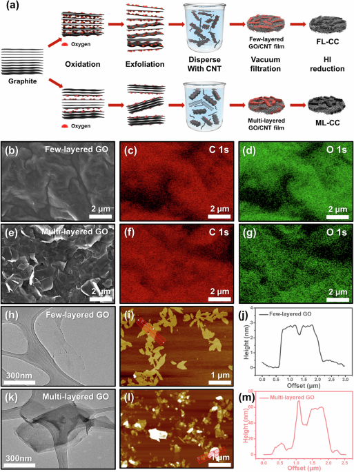
Figure 1a illustrates the overall fabrication process of the FL-CC and ML-CC. To synthesize the FL-CC and ML-CC, graphite is oxidized to graphite oxide with different oxidation states. The graphite oxdides are then exfoliated to GOs with varying layer counts, few-layered GO and multi-layered GO. Subsequently, the obtained GOs are disepersed with single-walled CNT (SWCNT) powder in aqueous sodium dodecyl sulfate (SDS) solution by tip sonication. The SWCNTs are added to provide sufficient mechanical strength and flexibility to form freestanding film. Then, GO-CNT films are fabricated via the vacuum filtrating the dispersed GO-CNT solution. After dipping each GO-CNT film in the hydrogen iodide (HI) solution, each FL-CC and ML-CC is prepared.

a Schematic illustration for fabrication process of FL-CC and ML-CC. b SEM image and c, d corresponding EDS mapping images of few-layered GO. e SEM image and f, g corresponding EDS mapping images of multi-layered GO. h TEM and i AFM images of few-layered GO. j Line profile of the red-boxed region in (i). k TEM and l AFM images of multi-layered GO. m Line profile of the red-boxed region in (l).
To synthesize the GOs with varying layer counts, graphite oxides with different oxidation states were first synthesized using the modified Hummers’ method with different amounts of KMnO4. To confirm whether the oxidation processes were successfully conducted, fourier-transform infrared spectroscopy (FT-IR) measurements were performed (Fig. S1). In the case of pristine graphite, no peak was observed except for the weak peak related to the C-C bond. However, as the oxidation state increased, the peak intensities of the oxygen-containing functional groups and the C-C bond significantly increased, indicating the successful synthesis of graphite oxides with different oxidation states35. Then, the obtained graphite oxides were bath-sonicated in DI water for 24 h to synthesize GOs with varying layer counts. During the sonication process, the graphite oxides were exfoliated to GOs owing to the electrostatic repulsion force of the oxygen-containing functional groups36,37. Therefore, the graphite oxides in higher oxidation states were exfoliated to few-layered GOs, whereas those in lower oxidation state were exfoliated to multi-layered GOs. To confirm if the GOs with varying layer counts are successfully synthesized, field-emission scanning electron microscope (FE-SEM)-energy-dispersive X-ray spectroscope (EDS) and Raman analyses were performed. As presented in Fig. S2, the few-layered GOs have similar morphologies to the single-layered commercial GOs. However, it is confirmed that the morphologies of the multi-layered GOs are different from those of the few-layered GOs, which is highly likely due to the difference in the graphene layer counts (Fig. 1b, e). The corresponding EDS mapping images showed that the few-layered GOs contained considerably more oxygen atoms than the multi-layered GOs, which was in line with the FT-IR results (Fig. 1c, d, f, g). Moreover, the Raman analyses further proved that the GOs were successfully synthesized as intended (Fig. S3). As shown in Fig. S3, in the low-oxidation state, the intensity ratio of the D band (near 1350 cm−1) to the G band (near 1600 cm−1) (D/G ratio) increases as the oxidation level increases. However, in the high-oxidation state, the D/G ratio decreases despite the increase in the oxidation level, which is line with typical Raman spectra of the GOs in high-oxidation states. Meanwhile, the full width at half maximum of the G-band increased as the oxidation level increased, which was also highly accordant with the typical Raman results of the GOs35,38. These results demonstrate that GOs with different oxidation states were synthesized.
To further investigate the number of the graphene layers of each GO, field-emission transmission electron microscope (FE-TEM) and atomic force microscope (AFM) measurements were conducted. The TEM images revealed that the exfoliated few-layered GOs were close to monolayers, while the exfoliated multi-layered GOs had multi-layered structures. (Fig. 1h, k). Also, similar results were confirmed via the AFM images. In the AFM images, the difference in the height of the GOs could be distinguished by the contrast of the graphene sheets. In the case of the few-layered GOs, all the graphene sheets of few-layered GOs had similar heights of 2–3 nm, which was estimated by one or two layers of graphene sheets (Fig. 1i, j). In contrast, the multi-layered GOs have a higher number of layers in overall sheets compared to the few-layered GOs, which is in agreement with the TEM images (Fig. 1l, m). From these results, it was confirmed that the GOs with varying layer counts were successfully synthesized.
Characterization of FL-CC and ML-CC
Figure 2a, d show the Raman spectra of both GO/CNT scaffolds before and after the reduction process. As presented in the Raman spectra, the D/G ratios of both scaffolds decrease after the reduction process, which is due to the decrease in the number of oxygen atoms on the surface of the GOs39. To increase the reliability of the Raman results, X-ray photoelectron spectroscopy (XPS) analyses were conducted (Fig. S4). To clearly observe the reduction effects on the GOs, the analyses were performed for pure few-layered and multi-layered GO/rGOs. Figure S4 show the deconvoluted O 1 s spectra of the GO/rGOs, confirming that oxygen-containing functional groups considerably decreased after the reduction process. These results demonstrate that the reduction processes were successfully carried out.
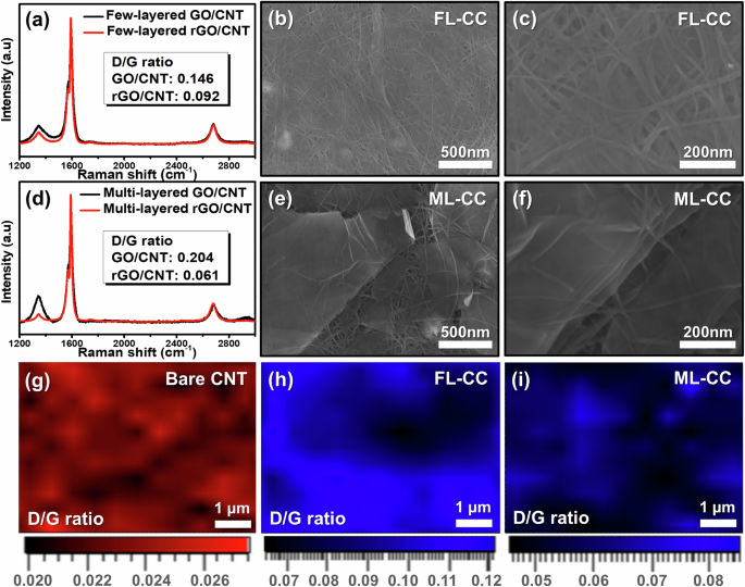
a Raman spectra of FL-CC before and after HI reduction process. b Top-view and c high-magnification SEM images of the FL-CC. d Raman spectra of ML-CC before and after HI reduction process. e Top-view and f high-magnification SEM images of ML-CC. Raman mapping images for D/G ratio of g bare CNT, h FL-CC, and i ML-CC.
Figure S5 show the photographic images of both prepared current collectors, exhibiting no significant difference in appearance and excellent flexibility. This is because the mechanical flexibility is primarily depending on the ratio composition of the SWCNT. Also, both FL-CC and ML-CC were bent without a noticeable damage after galvanostatic cycling, further demonstrating their excellent flexibility. To investigate the surface morphologies of the FL-CC and ML-CC, SEM measurements were conducted. Figure 2b shows the low-magnification SEM image of the FL-CC, which reveals similar morphologies to those of the pristine CNT scaffold (Figure S6). It is likely that the uniform distribution of few-layered rGO sheets across the surface hinders the clear observation of their morphologies in low-magnification SEM image. In the high-magnification SEM image of the FL-CC, the edge of few-layered rGO was confirmed, which indicated the existence of the few-layered rGOs (Fig. 2c). However, the ML-CC showed uniformly distributed multi-layered rGOs within the CNT scaffold (Fig. 2e). The high-magnification SEM image of the ML-CC also exhibited a similar morphology, which verified the presence of the multi-layered rGOs (Fig. 2f). To increase the validity of the SEM results, Raman mapping measurements were performed. Figure 2g depicts the Raman mapping image of the pristine CNT scaffold. It is observed that the D/G ratio of approximately 0.022 is uniformly distributed over the entire surface, which is consistent with the typical D/G ratio of SWCNTs40. Meanwhile, the FL-CC exhibits a higher D/G ratio of approximately 0.10 that is similar value with the Fig. 2a (Fig. 2h). This further demonstrates the presence of the few-layered rGOs uniformly distributed in the scaffold. Similarly, the ML-CC shows an D/G ratio of approximately 0.06, verifying the uniform distribution of the multi-layered rGOs throughout the entire scaffold (Fig. 2i). These results confirm the successful fabrication of both scaffolds with varying rGO layer counts.
Electrochemical performances in LMB tests
To evaluate the electrochemical performances of both current collectors, Li metal cell tests were conducted. Figures 3a and S7 present the cycling performances of the Li metal cells with Cu, CNT, FL-CC, and ML-CC current collectors (i.e., Li|Cu, Li|CNT, Li|FL-CC, and Li|ML-CC cells) at a current density of 1.0 mA cm−2 with an areal capacity of 1.0 mAh cm−2. Since the electrolyte used in the cell evaluation is the carbonate-based electrolyte without any additives, all the cells exhibit relatively poor CEs compared to the those with advanced electrolytes, which is attributed to severe parasitic reactions like continuous electrolyte decomposition and resulting accumulation of solid electrolyte interphase layer41,42,43. In the case of the Li|Cu cell, the CE gradually decreased and significantly fluctuated after 50 cycles, which was due to the uneven Li plating and dendritic Li growth during cycling. In contrast, the Li|CNT cell showed better cycling performance than the Li|Cu cell owing to the large specific surface area of the CNT that confines excess Li, however, it suffers a significant CE fluctuation after 150 cycles due to the inevitable dendritic Li growth. Meanwhile, the Li|FL-CC cell exhibited further improvement in cycling stability compared to the Li|CNT cell. This is highly likely due to the presence of the rGO layers that are more lithiophilic than the CNT, guiding uniform Li plating during cycling44,45. In addition, the Li|ML-CC cell delivered significantly improved cycling stability and higher CEs even compared to the Li|FL-CC cell. This favorable result is attributable to the hybrid Li storage of intercalation/plating of the ML-CC. During the initial lithiation process, the Li ions preferentially intercalate into the multi-layered rGO structures due to the lower intercalation energy compared to the adsorption energy on the rGO surface, which imparts lithiophilic properties to the ML-CC (Fig. S8). Then, the Li-intercalated multi-layered rGO structures with high lithiophilicity induces uniform Li deposition during the further lithiation process, enabling reversible electrochemical reactions46. In addition, the portion of Li stored by directly plating decreases in the ML-CC, which also contributes to achieve excellent electrochemical reversiblity during cycling. However, in the case of the FL-CC with few Li-intercalatable site, the majority of Li is stored by directly plating/stripping with causing severe irreversible active Li loss, delivering poor cycling stability. When the both cells were evaluated in an elevated current density of 4.0 mA cm⁻², the Li|ML-CC cell maintains superior cycling performance over the Li|FL-CC cell, further validating its improved reversibility (Fig. S9).
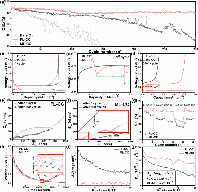
a Cycling performances of Li|Cu, Li|FL-CC, and Li|ML-CC cells. Voltage profiles of Li|FL-CC and Li|ML-CC cells at the (b, c) initial and d 300th cycle. EIS Spectra of e Li|FL-CC and f Li|ML-CC cells after 1 cycle and after cycling. g Rate performances of Li|FL-CC and Li|ML-CC cells at various current densities. h GITT curves and i corresponding IR drop values of Li|FL-CC and Li|ML-CC cells. j Li-ion diffusion coefficient values obtained from GITT tests.
Figure 3b presents the initial voltage profile of the Li|FL-CC and Li|ML-CC cells. In the Fig. 3b a voltage hump is observed in the Li|ML-CC cell between 0 and 0.1 V during the lithiation process, different from the Li|FL-CC cell. This voltage hump corresponds to the Li intercalation reaction in the current collector, which further verifies the occurrence of the Li intercalation into the multi-layered rGOs in the ML-CC47,48. Also, similar tendency is observed in the voltage profiles at the higher current density (Fig. S9b). To further demonstrate the difference in the Li storage mechanisms of each current collector, cyclic voltammetry (CV) measurements were conducted. Figure S10 shows the CV curves of each current collector after the first cycle. In contrast to the FL-CC, the ML-CC shows distinct reduction and oxidation peaks in the CV curves, which are in accordance with the typical Li intercalation/deintercalation peaks of graphite, proving that the Li intercalation/deintercalation reactions occur in the ML-CC49. In addition, SEM analyses were performed to visually observe the intercalation reaction on the ML-CC (Fig. S11). To confirm the lithiation mechanisms of each current collector, the Li metal cells with each current collector were disassembled after Li plating at 0.2 mAh cm−2 in the initial cycle (Fig. S11a, b). After Li plating, a Li layer was formed on the surface of the FL-CC with partially accumulated Li, compared to the SEM images before Li plating (Fig. S11c, d, g, h). However, the Li-intercalated multi-layered rGOs are observed on the ML-CC, which increases the reliability of the CV results (Fig. S11e, f, i, j). In addition, the bottom side of the ML-CC exhibits gold surface after Li plating noticeably different from the FL-CC, which is known as the color for graphitic structures after Li intercalation, demonstrating that the Li intercalation occurs throughout the overall portion of the ML-CC (Fig. S12).
To gain deeper insight into the excellent cycling stability of the Li|ML-CC cell, nucleation overpotential of each cell was compared, which is a good indicator of the lithiophilicity of the current collector (Fig. 3c)50. As shown in the Fig. 3c, the Li|ML-CC cell exhibits a noticeably lower nucleation overpotential (31.52 mV) than the Li|FL-CC cell (74.14 mV), revealing the high lithiophilicity of the ML-CC. This is because the lithiophilic nature of the ML-CC is ascribed to the Li-intercalated multi-layered rGO, which reduces the energy barrier for Li plating. These features result in the uniform Li plating/stripping behavior on the ML-CC, leading to excellent cycling stability. Figure S13a presents the voltage profiles of the Li|FL-CC and Li|ML-CC cells at the 150th cycle. It is confirmed that the intercalation reaction constantly occurs in the ML-CC after repetitive cycling. Also, the voltage hump is observed in the last voltage profile of the Li|ML-CC cell, indirectly demonstrating the excellent electrochemical reversibility of the ML-CC (Fig. 3d). In addition, the Li|ML-CC cell exhibits a lower voltage hysteresis (~137 mV) than the Li|FL-CC cell (~144 mV) at the 150th cycle, increasing the reliability that the reversible electrochemical reactions occur in the ML-CC (Fig. S13b).
To further investigate the electrochemical performances, electrochemical impedance spectroscopy (EIS) analyses were conducted after 1 cycle and after cycling for the Li|FL-CC and Li|ML-CC cells (Fig. 3e, f). In the EIS spectra, the charge transfer resistance (Rct) (semicircle in the higher frequency range) is a good indicator of the Li-ion reaction kinetics of the electrode. After the initial cycle, the Li|FL-CC cell exhibited an extremely high Rct (~700 Ω), indirectly demonstrating the poor reaction kinetics of the FL-CC. After cycling, the Rct drastically decreased to 160 Ω, which is originated from the dendritic Li growth that increases the surface area of the electrode51,52. Meanwhile, the Li|ML-CC cell exhibited a constantly lower Rct (~70 Ω) than the Li|FL-CC cell, even after repetitive cycling. These results indicate that the ML-CC has excellent electrochemical reversibility and superior Li-ion kinetics compared to the FL-CC owing to the hybrid Li storage mechanism and lithiophilic nature. To further verify the EIS analyses, rate capability tests were performed at current densities varying from 0.5 to 5.0 mA cm−2 (Fig. 3g). At a low current density of 0.5 mA cm−2, the Li|ML-CC cell exhibited a slightly higher CE than the Li|FL-CC cell. However, the Li|ML-CC cell exhibited significantly higher CEs than the Li|FL-CC cell at higher current densities. Furthermore, when the current density returned to 0.5 mA cm−2, the Li|ML-CC cell almost recovered its initial CE, while the Li|FL-CC cell delivered a decreased CE, which further demonstrates the excellent Li-ion reaction kinetics of the ML-CC.
To measure the Li-ion diffusivity of both current collectors, galvanostatic intermittent titration technique (GITT) tests were performed. Figure 3h, i present the GITT curves and the IR drop values of the cells with each current collector, respectively. Through the results, it is confirmed that the Li|ML-CC cell exhibits smaller IR drops than the Li|FL-CC cell owing to the reduced cell resistance. The Li-ion diffusion coefficient is calculated from the IR drop values using Eq. (1) (Fick’s second law):
$${D}_{{\mathrm{Li}}^{+}}=\frac{4}{\pi \tau }{\left(\frac{{m}_{B}{V}_{M}}{{M}_{B}S}\right)}^{2}{\left(\frac{{\Delta E}_{s}}{{\Delta E}_{t}}\right)}^{2}$$
(1)
where τ is the titration duration, S is the surface area, mB is the mass, MB is the molar mass, and VM is the molar volume of the current collector. Further, ΔEs and ΔEt denote the changes in voltage during the single relaxation and titration step. The average values of the \({D}_{{{\rm{Li}}}^{+}}\) for the Li|FL-CC and the Li|ML-CC cells were 2.54 × 10⁻¹⁰ and 5.25 × 10⁻¹⁰ cm2 s−1, respectively, which is in good agreement with th EIS and rate performance result (Fig. 3j). This result is attributed to the multi-layered rGO structures that enables hybrid Li storage mechanisms. Also, the multi-layered rGO structures have expanded intelayer spacing compared to pristine graphite due to the oxidation process of the graphite involved in the experimental process53,54. The expanded interlayer spacing significantly facilitates the Li-ion diffusion into the graphitic structures, which is known as remarkably slow process than Li-ion diffusion within the graphitic structure55,56. To further verify the Li-ion diffusion rate within the FL-CC and ML-CC, Tafel plot was derived from Linear Sweep Voltammetry (LSV) analysis (Fig. S14). The Tafel plot confirms that the ML-CC exhibits a higher exchange current (i0) than the FL-CC, reflecting the rapid Li-ion transport kinetics of the ML-CC. This result increases the validity of the high \({D}_{{{\rm{Li}}}^{+}}\) of the ML-CC.
Post-mortem studies
To investigate the Li plating behavior on FL-CC and ML-CC, finite element method (FEM) simulations were conducted in conjunction with density functional theory (DFT) calculations. The calculated adsorption energies for few-layered and multi-layered rGO were −4.37 and −4.48 eV, respectively, while the intercalation energies were −5.27 and −5.90 eV, respectively, as shown in Fig. S8. These negative values indicate that both Li adsorption on the rGO surface and intercalation within the bilayer structure are energetically favorable in both rGOs. Also, the larger magnitude of the intercalation energies compared to the adsorption energies indicates that Li ions preferentially intercalate into the bilayer structure rather than remain adsorbed on the surface. Furthermore, the results suggest that the multi-layered rGO can further enhance Li intercalation within the current collector compared to the few-layered rGO, resulting in efficient Li storage and thus uniform Li plating during cycling. These findings were clearly demonstrated in the Li plating behavior observed in the simulations, which were conducted under initial cycling conditions. (Fig. 4a, h). In the simulations, the intercalation effects of Li were considered by treating each current collector as a thin layer and incorporating diffusivity within it, using the diffusion coefficient value of each current collector. Detailed specific parameters and assumptions used in the modeling are summarized in Table S1 and Experimental section. The results show the distinct Li plating behaviors between the FL-CC and ML-CC. The FL-CC exhibits uneven Li plating on its surface, which can cause the Li dendrites growth. In contrast, the ML-CC effectively suppresses inhomogeneous Li plating on its surface, which is likely due to the multi-layered rGOs within the current collector that promotes efficient Li storage during cycling. Also, the hybrid Li storage mechanism of ML-CC, which allows a greater proportion of Li to be stored within the internal structure of the current collector, results in less Li being plated on the surface compared to the FL-CC. Moreover, given the high lithiophilicity of the ML-CC after initial Li intercalation, the ML-CC is expected to achieve more uniform Li plating during cycling. These results imply that integrating multi-layered rGOs within the current collector can result in uniform Li deposition and suppresses Li dendrites growth.
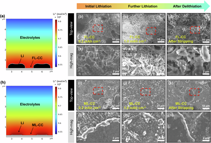
a Simulation result for Li plating behavior on FL-CC. Top-view SEM images of FL-CC after Li plating at (b, e) 0.2, (c, f) 1.0 mAh cm–2, and (d, g) Li stripping. (h) Simulation result for Li plating behavior on ML-CC. Top-view SEM images of ML-CC after Li plating at (i, l) 0.2, (j, m) 1.0 mAh cm–2, and (k, n) Li stripping.
To further confirm the Li plating/stripping behavior on each current collector, post-mortem studies were conducted after 10 cycles. Figure S15 presents the Li plating morphologies on the Cu current collector. When the Li was plated at 0.2 mAh cm−2, sharp and dendritic Li morphologies were confirmed owing to the low surface area and lithiophobic nature of the Cu current collector (Fig. S15a, d). As Li was plated further at 1.0 mAh cm−2, dendritic Li growth became more severe (Fig. S15b, e). In addition, the dendritic Li remained even after Li stripping, which resulted in the dead Li formation (Fig. S15c, f). In the case of the FL-CC, relatively mossy Li plating morphologies compared to the Cu current collector were confirmed at 0.2 mAh cm−2 of Li plating (Fig. 4b, e). This result is due to the large specific surface area of the 3D current collector, which reduces the local current density and confines excess Li within the current collector. However, as the extent of the Li plating increases, dendritic Li morphologies were also observed on the FL-CC (Fig. 4c, f). Furthermore, after Li stripping, the dead Li was formed over the entire area of the FL-CC owing to the irreversible Li storage and release (Fig. 4d, g). Different from the FL-CC, when Li was plated on the ML-CC at 0.2 mAh cm−2, smooth Li morphologies and Li-intercalated multi-layered rGOs were confirmed, which is consistent with the simulation results (Fig. 4i, l). These Li-intercalated multi-layered rGOs with high lithiophilicity facilitate uniform Li plating, serving as a Li-ion redistributor that spreads the Li ions uniformly across the surface of the ML-CC46,57,58. Moreover, even when the lithiation extent increases to 1.0 mAh cm−2, the uniform Li plating morphologies remained with suppressing the Li dendrites growth, which is attributed to the hybrid Li storage mechanism of the ML-CC (Fig. 4j, m). Similarly, a clear surface without the dead Li formed was confirmed on the ML-CC after the Li stripping process, demonstrating that reversible storage and release occur in the ML-CC. (Fig. 4k, n). To further verify the effect of the hybrid Li storage mechanism on the Li plating/stripping behavior, the Li|FL-CC and Li|ML-CC cells were disassembled after cycling. Figures S16a and S16d present the photographic images of the FL-CC and ML-CC after cycling, respectively. As illustrated in the photographic images, the cycled FL-CC exhibits an uneven surface with bumpy Li deposits, whereas the ML-CC cycle has a more uniform surface than the FL-CC. Moreover, similar results were confirmed from the SEM images of both cycled current collectors. Severe Li dendrites were observed on the overall surface of the cycled FL-CC, while the dendritic Li growth was noticeably suppressed on the surface of the cycled ML-CC, further proving the reversible electrochemical reactions of the ML-CC (Figs. S16b, c and S16e, f).
Electrochemical performances of FL-CC and ML-CC in anode-free LMBs
To investigate the electrochemical performances of the FL-CC and ML-CC in practical conditions, each current collector was evaluated in an LMB with anode-free condition (anode-free LMB) using an LFP cathode with a high areal capacity (~4.5 mAh cm−2). All the anode-free LMBs were evaluated in the carbonate-based electrolytes. Figure 5a presents the cycle performances of the anode-free LMBs with FL-CC and ML-CC (i.e., LFP | FL-CC and LFP | ML-CC cells) at a current density of 0.15 C. At the first cycle, the LFP | ML-CC cell exhibited a higher CE of 91.09% compared to the LFP | FL-CC cell (89.74%). Also, the LFP | ML-CC cell showed superior electrochemical performance (average CE of 98.09% and capacity retention of 41.33% after 50 cycles) than the LFP | FL-CC cell (average CE of 97.17% and capacity retention of 26.15% after 50 cycles) owing to the hybrid Li storage mechanism of the ML-CC. The hybrid mechanism promotes uniform deposition of the initial Li layer, leading to subesequent Li deposition more homogeneous compared to the FL-CC. Also, the uniformly deposited Li results in reduced parasitic reactions with the electrolyte and thus diminishes the acitve Li-ion loss during cycling, which is especially crucial for the anode-free LMBs with limited Li sources. Figure S17a, b display the voltage profiles of the LFP | FL-CC and LFP | ML-CC cells. As shown in the voltage profiles, the LFP | FL-CC cell suffered a rapid capacity decay upon cycling, when compared to the LFP | ML-CC cell. Moreover, the LFP | ML-CC cell exhibited much lower voltage hysteresis than the LFP | FL-CC cell, further demonstrating the excellent electrochemical reversibility of the hybrid Li storage mechanisms (Fig. S17c).
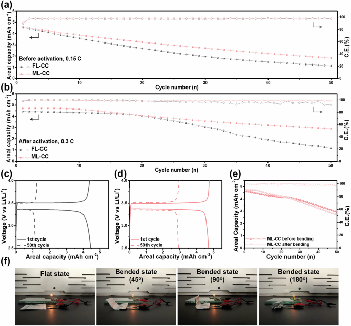
a Cycling performances of LFP | FL-CC and LFP | ML-CC cells at 0.15 C before activation process. b Cycling performances of LFP | FL-CC and LFP | ML-CC cells at 0.3 C after activation process. Voltage profiles of c LFP | FL-CC and d LFP | ML-CC after activation process for the initial and final cycle. e Cycling performances of ML-CC before and after bending in anode-free LMB. f Photographic images of pouch cell with ML-CC, powering an lightbulb under various bending conditions (flat, 45°, 90°, and 180°).
Typically, the irreversible active Li-ion loss caused by side reactions at the initial cycles is one of the main reasons for the rapid capacity decay of the anode-free LMBs. In order to compare the cycling stability of the anode-free LMBs using each current collector with reduced side reactions and stabilized surface, pre-activation processes were conducted before the cell fabrication59. For the pre-activation processes, the cells were cycled at a low current density with multiple cycles21. After the activation process, the LFP | ML-CC delivered excellent cycling performance of a capacity retention of over 80% after 50 cycles with an average CE of 99.15%, which is more stable than that of the LFP | FL-CC cell (capacity retention of 71.5% and average CE of 98.92%) (Fig. S18). Likewise, similar results were obtained when each cell was evaluated under a harsher test condition of 0.3 C (Fig. 5b–d). Even after the activation process, the LFP | FL-CC cell suffered a rapid capacity decay from 20 cycles with fluctuating CEs. This is attributed to the irreversible Li storage/release of the FL-CC, which results in the dead Li formation and active Li-ion loss during cycling. However, the LFP | ML-CC cell retained a stable cycling performance even at the high current density, further highlighting the excellent electrochemical reversibility of the hybrid Li storage mechanism. In conclusion, these results demonstrate that the electrochemical performances of the anode-free LMBs can be significantly improved by incorporating reversibly lithiatable materials into the current collectors.
To validate that ML-CC maintains consistent performance under mechanical deformation, cycling stability of anode-free LMBs employing the ML-CC before and after multiple bending cycles was compared (Fig. 5e). The ML-CC exhibited nearly identical CE and capacity retention in both cases, demonstrating its structural flexibility and mechanical reliability. To further demonstrate the mechanical flexibility of ML-CC as a current collector, pouch-type cells were fabricated and evaluated under various mechanical deformation states. The cells were connected to a lightbulb and tested in the flat state as well as after being bent to 45°, 90°, and 180°. In all cases, the lightbulb operated successfully, confirming the stable electrical performance of the ML-CC (Fig. 5f). Moreover, voltage profiles obtained from galvanostatic cycling before and after bending were nearly identical, further supporting the mechanical durability of the ML-CC as the current collector (Fig. S19).
Figure 6 illustrates how the incorporation of reversibly lithiatable materials within the current collector enhances the electrochemical reversibility of Li storage and release processes in Li-metal-based batteries. In the FL-CC, Li ions are directly plated onto the surface rather than being intercalated into the carbon structure of the current collector. This leads to the formation of inhomogeneous Li nuclei, which further promotes severe dendritic Li growth during charging. The formation of dendritic Li on the surface of the FL-CC not only elevates the risk of internal short circuits but also contributes to rapid capacity fading due to the accelerated loss of active Li. In contrast, the ML-CC incorporating reversibly lithiatable materials, the multi-layered rGO, allows for Li-intercalation during the initial stage of lithiation. This Li-intercalation process imparts lithiophilic properties to the backbone of the ML-CC, enhancing its surface affinity for Li ions. As a result, Li ions are more uniformly distributed within the current collector, promoting uniform Li plating during subsequent charging cycles. Then, the dendritic Li growth and formation of dead Li on the ML-CC is effecitvely suppressed. Consequently, the ML-CC achieves a highly reversible Li storage and release process, leading to excellent cycling stability. The improved performance of the ML-CC highlights the importance of incorporating reversibly lithiatable materials within the current collector.
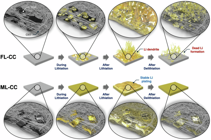
Schematic illustration to explain the roles of reversibly lithiatable materials within the scaffold on Li plating/stripping behavior on FL-CC and ML-CC.
link


More Stories
OE-A Highlights Flexible and Printed Electronics at productronica 2025
New PU/PEG-MXene nanocomposites for flexible electronics
Chinese scientists propose ‘drop-printing’ strategy, providing technical support for flexible electronics, BMI: institute