Fabrication and optimization of the textile platform
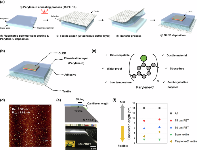
A textile substrate with a characteristic weave pattern exhibits roughness on the micron scale, which makes it difficult to operate OLEDs with thicknesses in the range of hundreds of nanometers27. Therefore, a simple transfer process was devised to planarize the roughness of the polyester textile to the nanometer scale, as shown in Fig. 1a.

a Fabrication procedure for the textile platform. b Schematic illustration of the textile-based OLED structures. c Parylene-C properties for the planarization layer. d Surface roughness of the textile platform measured by AFM. e Schematic diagram (top) and photograph (bottom) of the cantilever test (ASTM D:1388) demonstrating the flexibility of the textile platform. f Cantilever lengths of various substrates as measured by the cantilever test.
To create a smoother planarization layer, a surface-replicating method was employed to replicate a glass-like flat surface, as described in previous studies16. First, a fluorinated polymer was coated as a sacrificial layer to remove parylene-C more easily from the guide glass. Then, a parylene-C film with a thin thickness of 3 μm, intended for use as the planarization layer, was deposited using a chemical vapor deposition (CVD) process. The parylene-C planarization layer was easily removed and transferred from the guide glass due to the presence of the fluorinated polymer. The low surface energy of the fluorinated polymer allows for easy physical transfer without damaging other layers or the textile, providing a simple fabrication method that does not necessitate submerging the textile in water or the use of any chemical agents. In cases where high-temperature processes are required or the fabrication process is complex, making direct fabrication on textiles difficult, devices can be pre-fabricated on the guide glass/parylene-C and then transferred to the textile. This method is crucial for the future integration of many devices onto textiles.
Next, thermal annealing at 150 °C for 1 h was employed to increase the stiffness of the parylene-C. Thermal annealing is essential to obtain a flat surface, as the inherent low stiffness properties of parylene-C cause it to conform to the rough surface of the textile when transferred immediately after deposition. After annealing, the parylene-C intended for use as the planarization layer was attached to the textile as an adhesive and strain buffer layer. A Si-based elastomeric room temperature vulcanizing (RTV) material was utilized as the strain buffer layer through a spin-coating process16. This strain buffer layer can be naturally cured at room temperature, and due to its low 18 Shore A hardness, which is softer than a rubber band, the strain on the textile substrate caused by movement is reduced, thereby ensuring better flexibility16. Subsequently, after the adhesive layer cures at room temperature, the parylene-C is transferred to the textile to form a planarization layer. To protect the organic material from moisture and air, a bottom encapsulation structure was first applied. This bottom encapsulation consisted of a 30 nm Al2O3/ZnO nano-stratified structure deposited via an atomic layer deposition (ALD) process at 70 °C37. Next, the OLED was fabricated using a thermal evaporation process. Subsequently, a top encapsulation layer was deposited to further enhance device protection. The top encapsulation, similar to the bottom encapsulation, comprised an Al2O3/ZnO nano-stratified structure (30 nm) and a parylene-C layer (500 nm), ensuring protection for both the top and bottom of the device. This encapsulation structure effectively ensures comprehensive protection for both the top and bottom of the device, significantly enhancing the durability and environmental resistance of the textile-based OLED. The overall structure as shown in Fig.1b is composed of a commercially available 100% polyester type of textile, with a 19 μm adhesive and strain buffer layer and a 3 μm parylene-C planarization layer sequentially applied. Each layer thickness in this textile substrate was optimized based on experimental validation, theoretical analysis, and simulation results, as detailed in Supporting Note 1.1. This optimization process ensures the stability and mechanical compatibility of the textile-based OLED.
As shown in Fig. 1c, parylene-C has been implemented in various fields, such as micro-electromechanical systems (MEMS)38, sensors39, biomedical electronics31,40 and circuits, due to its diverse advantages. Additionally, the flexibility and biocompatibility required for textiles are provided by parylene-C, making it suitable as a planarization layer. Furthermore, its waterproof properties41 can provide an encapsulation42 effect for organic electronic devices vulnerable to water and oxygen.
Most importantly, parylene-C is a stress-free material and a semi-crystalline polymer with easily tunable mechanical properties, allowing its crystallinity and Young’s modulus to be easily enhanced through a thermal annealing process. Therefore, after annealing, parylene-C can maintain its structural integrity and function as a very thin but effective self-supporting planarization layer, even when transferred onto textile with a rough surface. The roughness of the fabricated planarization layer is shown in the atomic force microscopy (AFM) image in Fig. 1d, with Rrms (root-mean-square surface roughness) and Ra (average surface roughness) values measured at 1.89 nm and 1.37 nm, respectively. This demonstrated that a planarization layer can be easily and quickly implemented through the simple transfer process of the parylene-C layer, achieving a level of roughness that allows for the stable operation of very thin OLEDs.
Next, to assess the impact of the planarization layer on the flexibility of the textile, a simple cantilever test was conducted to measure the flexural rigidity of the textile. As illustrated in the schematic image in Fig. 1e, the cantilever test involved pulling the textile specimen along an inclined plane, at which point the length at which the specimen, driven by gravity, came into contact with the plane was measured. Higher flexibility is indicated by a shorter contact length, while greater stiffness is indicated by a longer contact length, as demonstrated by the results shown in Fig. 1f. To demonstrate the flexibility of the textile with parylene-C as the planarization layer, various substrates ranging from A4 paper to PET films with different thicknesses were measured and compared with untreated bare textiles. In the graph shown in Fig. 1f, instances where the planarization layer is on top of the textile are represented by the points on the left, and instances where the planarization layer is beneath the textile are represented by the points on the right. Despite the significantly greater thickness of the textile compared to other substrates such as PET or A4 paper, a much shorter cantilever length results from the inherent flexibility of the textile. It is also demonstrated that the planarization process maintains flexibility similar to that of the untreated bare textile. This confirms that the intrinsic flexibility of the textile was successfully preserved while implementing the planarization layer.
Optimization of the parylene-C for planarization layer
To ensure that ultra-thin and flexible OLEDs with thicknesses of hundreds of nanometers can operate stably on a textile substrate, a very thin self-supporting planarization layer was created to form a flat surface with sub-nanometer roughness and to prevent a collapse following the surface curves of the textile. Parylene-C is particularly noteworthy among various materials due to its biocompatibility, stress-free nature, and ease of property modification as a semi-crystalline polymer. The crystallinity and mechanical properties of parylene-C films can be altered through thermal annealing, making these films very convenient for achieving desired characteristics. Without the annealing process, parylene-C inherently has low stiffness. If used directly as a planarization layer without this process, it would conform to the surface curves of the textile, leading to instability and unreliable operation of ultra-thin OLEDs. To address this issue, a thin self-supporting planarization layer that does not collapse under the weave pattern was constructed. To ensure a stable self-supporting planarization layer for OLEDs, the crystallinity and Young’s modulus of parylene-C were enhanced through annealing. The annealing process, conducted at 150 °C for 1 hour, improved the crystallinity, as verified by an X-ray Diffraction (XRD) analysis. As shown in Fig. 2a, the annealed parylene-C films exhibit increased crystallinity due to relaxation and rearrangement in the amorphous regions of the polymer, resulting in higher peaks in the same direction. The crystallinity of each film was calculated for a quantitative comparison using the following equation43,44.
$${X}_{C}=\frac{{A}_{C}}{({A}_{C}+{A}_{A})}\times 100\left( \% \right)$$
(1)
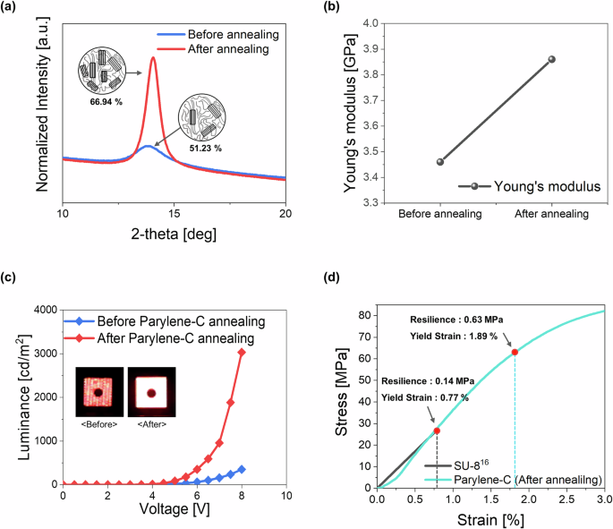
a Crystallinity measured by XRD. b Young’s modulus measured by the tensile test, comparing parylene-C films before and after thermal annealing. c Voltage (V)-luminance (L) graph of textile-based OLEDs before and after parylene-C film annealing for utilization as a planarization layer (inset: cell images of textile based-OLEDs). d Mechanical characteristics of the resilience and yield strain along the stress-strain curves of the parylene-C films measured in this study and in SU-8 films in a previous study16.
In this equation, \({A}_{C}\) represents the area under the crystalline peak, and \({A}_{A}\) represents the area under the amorphous region, calculated by integrating the area under the graph. The calculated crystallinity increased from 51.23% before annealing to 66.94% after 1 h of annealing at 150 °C. This increase in the crystallinity leads to higher tensile strength and greater overall stiffness. To verify the changes in the mechanical properties of parylene-C after annealing, tensile tests were conducted on samples before and after annealing at 150 °C for 1 h. (Supplementary Fig. 2a). The Young’s modulus was calculated by determining the slope of the linear region in the elastic range. The Young’s modulus of parylene-C before and after annealing were measured to be 3.46 GPa and 3.86 GPa, respectively (Fig. 2b). This indicates an ~11% increase in the Young’s modulus post-annealing, indicating an increase in the material’s stiffness and thus, enabling the construction of a self-supporting planarization layer that does not conform to the surface curves of the textile. When parylene-C was applied as a planarization layer without annealing, the deposited OLED followed the weaving pattern of the textile and did not operate stably, as shown in the inset of Fig. 2c. However, after annealing, the OLEDs exhibited stable operation. This demonstrates that the semi-crystalline properties of parylene-C, which are enhanced through annealing to improve the crystallinity and Young’s modulus, are effective. Thus, using annealed parylene-C films as a planarization layer provides stable support for textile-based OLEDs, as shown in Fig. 2c.
After confirming that a thin self-supporting planarization layer was successfully formed and enabled stable operation of OLEDs, an additional evaluation was conducted to investigate the mechanical properties and to determine whether it would withstand external mechanical deformations. Given that textiles often experience stress concentrations from body movements or external mechanical deformations, high resilience is required to prevent the planarization layer from breaking and impacting the devices fabricated on top of it. Therefore, it was compared with a SU-8 textile planarization layer used in previous studies16. Firstly, to evaluate the material’s capacity to absorb and release elastic strain energy within the elastic region, which indicates resilience45, the area under the stress-strain curve up to the yield stress was calculated using the following equation46.
$${{\rm{U}}}_{r}={\int }_{0}^{{\varepsilon }_{y}}\sigma\,d\varepsilon$$
(2)
To determine the yield strength (σy) and yield strain (εy), the intersecting point between the stress–strain curve and a line parallel to the slope of the linear region, starting at an offset of 0.2%47, was identified, as indicated by the red circles in Fig. 2d (Supplementary Fig. 2b). Additionally, for a comparison with the characteristics of the SU-8 planarization layer used in previous work16, the stress-strain curves measured in previous studies were plotted, as shown in Fig. 2d. The yield strength, yield strain and resilience of parylene-C after annealing were 65 MPa, 1.89%, and 0.63 MPa, respectively, which were ~2.5, 2.45, and 4.5 times higher than those of SU-8, which were 26 MPa, 0.77%, and 0.14 MPa, respectively. These measurements are summarized in Table 1. These results indicate that employing parylene-C instead of SU-8 as a textile planarization layer increases the resilience by ~4.5 times, enhancing the resistance to significant external deformations. This improvement ensures that the material does not easily degrade and maintains a balance between stiffness and reliability, as required for planarization layers, significantly enhancing robustness against bending and wrinkling. The detailed mechanical performance based on these results is explained in Figs. 4 and 5.
In summary, the 3 μm thin parylene-C, after the annealing process, enhanced its Young’s modulus and higher yield strength, thereby increasing the stiffness to create a self-supporting planarization layer that does not follow the roughness of the textile. Additionally, compared to the SU-8 planarization layer used in previous studies16, improved resilience was achieved, allowing the textile planarization layer to withstand various and severe mechanical deformations.
Electrical and optical performance of parylene-C planarization textile-based OLEDs
The textile substrate was fabricated and then used for the thermal deposition of top-emitting red OLEDs. The OLEDs with a micro-cavity effect were composed of several layers, with aluminum (Al) as a cathode, lithium quinolate (Liq) as an electron injection layer, bis(10-hydroxybenzo[h]quinolinato)beryllium (Bebq2) doped with Tris[1-phenylisoquinolinato-C2,N] iridium(III) (Ir(piq)3) at 8 wt% as the red-light-emitting layer, N,N’-bis(naphthalen-1-yl)-N,N’-bis(phenyl) benzidine (NPB) as the hole transport layer, molybdenum trioxide (MoO3) as the hole injection layer, and silver (Ag) as the anode.
To confirm the light-emitting characteristics, Fig. 3 presents the optical and electrical properties of the optimized textile-based OLEDs with a device area of 9 mm². The micro-cavity structure was optimized using MATLAB-based Transfer Matrix Method (TMM) optical simulations to achieve a peak emission wavelength closely matching the photoluminescence (PL) peak (625 nm) of the dopant Ir(piq)₃. The optimization involved varying the thickness of the hole transport layer (NPB), and while the simulations predicted an optimal thickness of 63 nm, slight experimental deviations during fabrication resulted in the deposition of NPB at 62 nm. As shown in Fig. 3d, the fabricated textile-based OLED exhibited a peak emission wavelength of 623 nm. The optimized textile-based OLED demonstrated optimal performance, achieving a current efficiency of 23.8 cd/A and a maximum luminance of 12,748 cd/m² (Fig. 3a–c). Additionally, to evaluate the comparative performance, the optical and electrical characteristics of the textile-based OLEDs were compared with those of glass-based OLEDs. As shown in Supplementary Fig. 3, both devices exhibited similar optical and electrical properties, indicating that the parylene-C planarization layer effectively adapted to the rough textile surface and provided reliable device performance.
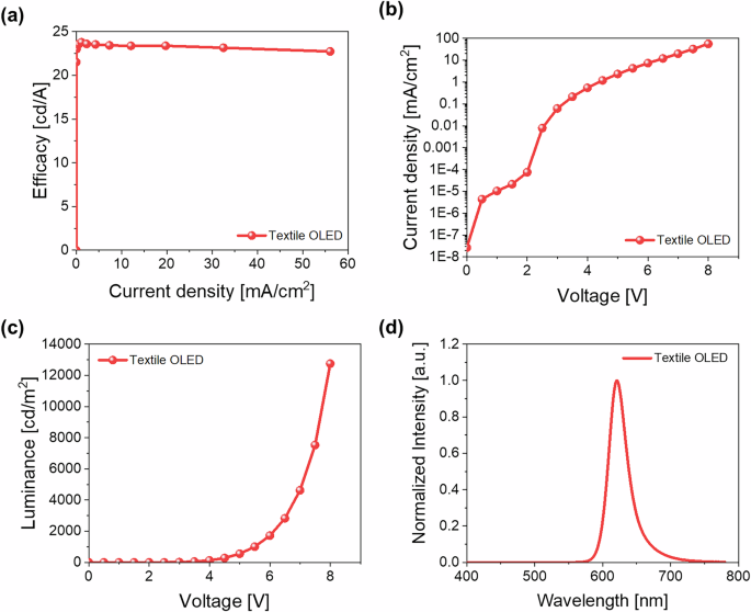
Representative device performance (a) current density-current efficacy curve, b voltage (V)-current density (J) curve, and (c) voltage (V)-luminance (L) curve, all tailored to the cavity peak (623 nm) optimization. d Normalized electroluminescence of the red-colored and textile-based OLEDs.
To protect the performance of the fabricated textile-based OLEDs from environmental factors, an encapsulation layer consisting of an Al₂O₃-ZnO nano-stratified layer (30 nm) and a parylene-C film (500 nm) was applied to the top surface of the device. Subsequently, the potential impact of the encapsulation layer on the optical properties of the OLEDs was thoroughly examined (Supplementary Fig. 4). The transmittance of the encapsulation layer slightly decreased compared to bare glass due to minor interference effects but maintained a relatively high level of 85–90% without significant oscillations (Supplementary Fig. 4a). Particularly, in the emission wavelength range of the red OLED (620–630 nm), the transmittance remained around 90%, ensuring that optical losses were negligible. The current density (J)-luminance (L) characteristics (Supplementary Fig. 4b) showed no significant differences in luminance between devices with encapsulation (w/ encapsulation) and without encapsulation (w/o encapsulation), confirming negligible impact on optical performance. Furthermore, angular dependency measurements revealed sub-Lambertian emission characteristics, caused by the cavity structure, rather than the typical Lambertian emission profile, with or without encapsulation having an insignificant influence on the angular characteristics (Supplementary Fig. 4c). This demonstrates that the encapsulation layer does not significantly degrade the optical performance while effectively supporting the stable operation of textile-based OLEDs under real-world application conditions.
To comprehensively evaluate the reliability of the encapsulated textile-based OLEDs, a series of tests were conducted under various environmental conditions (Supplementary Fig. 5). As shown in Supplementary Fig. 5a, the operating lifetime of the devices was measured under continuous wave operation in an ambient environment to assess their durability. The encapsulated OLEDs exhibited an operating lifetime more than five times longer compared to devices without encapsulation, demonstrating the significant effectiveness of the encapsulation structure in enhancing device stability. Following this, further testing was conducted under high-temperature and high-humidity conditions9 (30 °C, 90% RH (relative humidity)), as depicted in Supplementary Fig. 5b. The encapsulated OLEDs maintained 80% of their initial luminance over 160 h, whereas non-encapsulated devices exhibited rapid luminance degradation within the first 40 h, highlighting the critical role of encapsulation in preserving performance under harsh environmental conditions. Lastly, a water-storage test was conducted by immersing the OLEDs in water to evaluate their resistance to moisture and the performance of the encapsulation (Supplementary Fig. 5c). Devices without encapsulation failed immediately due to reactions between the organic layers and water. In contrast, encapsulated devices maintained 60% of their initial luminance for up to 120 h, thereby confirming the robust water and oxygen barrier properties provided by the encapsulation structure. These results collectively demonstrate that the encapsulation structure has negligible impact on the optical properties while effectively protecting the OLEDs from environmental challenges, ensuring their stability and performance under conditions such as prolonged exposure to moisture, ambient operation, and elevated humidity and temperature. This highlights the feasibility of the encapsulation structure for improving the reliability of textile-based OLEDs in real-world applications.
Mechanical performance of parylene-C planarization textile-based OLEDs
Textiles worn in everyday life have to withstand mechanical deformations such as bending or wrinkling. Therefore, to assess the mechanical reliability of textile-based OLEDs with a parylene-C planarization layer, bending and wrinkling tests were conducted, as shown in Fig. 4 and Fig. 5. The bending test, as shown in Fig. 4a, was implemented by clamping the parylene-C planarization textile-based OLEDs to a bending machine and varying the bending radius over 1000 cycles. Photographic images of the top and side views at a bending radius of 1.25 mm are also presented. The current density (J)-luminance (L) characteristics of the OLEDs before and after 1000 cycles at bending radii of 1.5 mm and 1.25 mm, respectively, indicated no performance degradation, as shown in Fig. 4b, c. Additionally, the bending radius was progressively reduced from 3 mm to 1.25 mm under increasingly harsh conditions, and the OLED characteristics were measured and expressed as the ratio of the luminance to the current density (L/J). The ratio of the luminance to the current density is represented as the slope in the current density-luminance graph in Fig. 4b, c. Identical values before and after bending indicate that the same degree of luminance is achieved at the same current input. Thus, it is confirmed that textile-based OLEDs with bending radii ranging from 3 mm to 1.25 mm exhibit minimal performance changes, thereby demonstrating high mechanical reliability. Additionally, the mechanical properties under multi-directional wrinkling, which can occur randomly due to daily movements, were evaluated (Fig. 5). For the wrinkling test, the devices were fabricated in a large size of 69 mm² to induce maximum deformation. As shown in Fig. 5a and supplementary Fig. 6, a multi-axis tensile test machine was used, with the corners of the textile clamped by alligator clips. The relative cell area was reduced by moving the clips toward the center. The detailed method, illustrated in Fig. 5b, involved starting with an initial cell area of 225 mm² set as 100% and progressively reducing the relative cell area due to wrinkling until it reached 28%. The wrinkled textile deformed into various shapes such as pop-down, random, and pop-up shapes, instead of uniformly bending (Fig. 5c). The wrinkling test was repeated 100 times, and the results are shown in Fig. 5d and Fig. 5e. After the wrinkling test, with the relative cell area decreased from 75% to 53%, no change in the luminance was observed after 100 cycles. However, for the SU-8 planarization layer utilized in previous studies16, as indicated by the dotted line, a slight initial decrease in the luminance was observed during wrinkling cycles, but it remained stable up to 100 cycles, with no measurements reported for more severe wrinkling. On the other hand, for the textile-based OLEDs using the parylene-C planarization layer, when the relative cell area decreased to 36%, the device maintained its performance for up to 50 cycles but ceased to operate after further repeated wrinkling. Moreover, at a relative cell area of 28%, the luminance decreased by more than 50% after 50 cycles and subsequently ceased to function. As depicted in the photographic images on the right in Fig. 5d, more significant deformations occurred as the relative cell area was decreased. Wrinkling induced a non-uniform strain distribution and concentrating high strain in localized areas, degrading the performance16. The emission images of OLEDs after each wrinkling cycle and at various relative areas are presented in Fig. 5e. These results validate that the enhanced resilience, as previously discussed, allows for greater deformation within the elastic region, thereby increasing the resistance to deformation. This confirms that textile-based OLEDs with a parylene-C planarization layer can maintain stable operation under extreme deformations, not only due to body movements and bending in everyday life but also under more severe mechanical deformations.
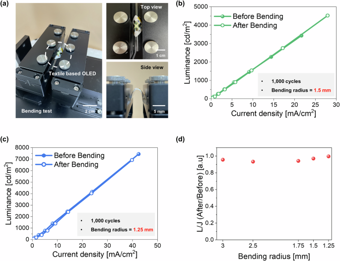
a Photographs (top and side view) of the textile-based OLEDs during repetitive bending with a 1.25 mm curvature radius. Current density (J)-luminance (L) graph according to a repetitive bending test of the textile-based OLEDs before and after bending under a bending radius of (b) 1.5 mm and (c) 1.25 mm, 1000 cycles, respectively. d Ratio of the luminance to the current density (the slope in the current density- luminance graph) at bending radii ranging from 3 mm to 1.25 mm.
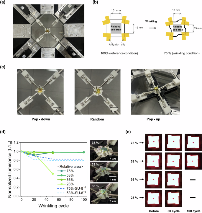
a Photograph of the multi-axis tensile test machine used for the multi-directional wrinkling test. b Schematic image of the wrinkling test condition according to the relative cell area (reference condition: relative area 100% and wrinkling condition: relative area 75–28%). c Photograph of various wrinkled shapes (left: pop-down, middle: random, and right: pop-up). d Normalized luminance of the repetitive wrinkling cycle of parylene-C textile in this study (solid line) and SU-8 textile in a previous study (dotted line)16, the initial luminance: 1000 nit. e Photograph of a parylene-C textile-based OLED cell after wrinkling (relative area: 75, 53, 36 and 28%, wrinkling cycles: 0 (before), 50 and 100 cycles).
Additionally, the mechanical performance of textile-based OLEDs under stretching conditions, along with bending and wrinkling tests, was evaluated. As shown in Supplementary Fig. 7b, the device retained over 70% of its initial efficacy under a 4% stretching strain, despite a slight efficiency reduction attributed to current aggregation, while luminance remained stable. However, as shown in Supplementary Fig. 7a, cracks were observed under strains exceeding 5%, resulting in device failure. While the stretchability of the proposed device is currently limited, these results demonstrate that its performance exceeds the reported stretching limit (~1%) of conventional encapsulation technologies48. This suggests that the proposed technology provides relatively greater stretching tolerance, even with 100% polyester textiles that inherently lack significant stretchability. These findings indicate that, in its current form, the proposed textile OLED technology is more suitable for applications where flexibility and mechanical stability take precedence over stretchability, such as healthcare, wearable displays, and fashion devices. Furthermore, this study highlights the potential for future improvements in stretchability through techniques such as reactive ion etching (RIE)-based patterning of the planarization layer, paving the way for advanced stretchable OLED technologies.
Demonstration of textile-based OLEDs
In this study, textile-based OLEDs were fabricated directly onto textile with a parylene-C planarization layer using a top-emission structure. These OLEDs can be utilized in two configurations. First, as shown in Supplementary Fig. 8a, light is emitted directly into the air, resulting in clear and bright emission, although the wiring lines and electrodes remain exposed due to the deposition process. Second, as depicted in Supplementary Fig. 8b, a sandwich structure is employed where an additional bare textile is placed over the pre-fabricated textile-based OLED, allowing the light to pass through the textile. This configuration conceals the wiring lines and electrodes but may cause light diffusion or an intensity reduction. Both modes were demonstrated in this study. To demonstrate an actual textile-OLED display, a 3 × 3 textile-based OLED array was arranged to display the letters “KAIST,” as shown in Fig. 6. A microcontroller unit (MCU, Arduino Uno) was connected to the textile-based OLED to enable passive matrix control, and the device was driven using a line-scanning method at 5 V. In Fig. 6a, a sandwich structure was created by adding a bare textile layer on top of the fabricated textile-based OLED to prevent exposure of the electrodes and wiring lines. This structure ensures a very neat appearance by completely concealing the wiring, although some light diffusion was observed due to the light passing through the textile. In contrast, the light from the OLEDs was emitted directly without an additional textile layer in Fig. 6b, similar to the structure shown in supplementary Fig. 8a, demonstrating stable operation even when the textile was wrinkled beyond natural folds (supplementary Movie S1). Lastly, a dog’s scarf was used to demonstrate the potential for practical applications in fashion displays (Fig. 6c, supplementary Movie S2). The scarf was placed around the neck of a stuffed dog, displaying desired text via passive matrix driving, similar to that shown in Fig. 6a, b. This textile display can present a range of information such as names, the weather, and the time, confirming its capability as a true wearing display that operates stably even under extreme wrinkling without causing discomfort.
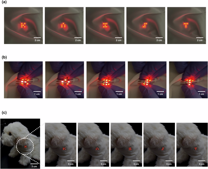
a Demonstration of the textile-based OLEDs presenting the word “KAIST”. b Stable operation under wrinkled conditions. c Scarf demonstration showcasing practical applications in smart fashion displays.
The proposed textile-based OLED technology is not only suitable for fashion displays but also shows great potential for other practical applications. For instance, it can be applied to wearable healthcare devices and phototherapy. By replacing conventional heavy and rigid point light sources, lightweight, flexible, and comfortable textile-based OLED masks have been demonstrated as an ideal solution for phototherapy49. These masks emit specific wavelengths of light, offering promising results for skincare and treatment while ensuring user comfort and accessibility. Moreover, the proposed OLED technology holds significant potential in the field of healthcare. Devices measuring biometric data such as heart rate and oxygen saturation can be integrated with textile-based displays to provide real-time feedback directly on the textile. This integration represents a user-friendly platform that combines convenience with efficiency, paving the way for advanced wearable healthcare systems. Additionally, the fabrication method proposed in this study supports scalability for large-area displays. As shown in Supplementary Fig. 9, OLEDs exceeding 4225 mm² were successfully fabricated using laboratory-scale deposition equipment, demonstrating stable operation. These results indicate that the textile substrate possesses high flatness and mechanical stability even under bending conditions. This scalability suggests the potential for industrial-scale production using advanced deposition systems, enabling broader applications in large-area displays.
To further validate the practicality of the proposed textile-based OLEDs, thermal performance was evaluated under various luminance conditions (Supplementary Fig. 10). PM-driving was conducted at 5 V with a 3 × 3 OLED array, and additional thermal evaluations were performed across a wide range of luminance levels to simulate practical usage scenarios. Operating temperatures were assessed at typical luminance levels (300–500 nit), outdoor visibility levels (1000 nit), and maximum luminance (5000 nit). The corresponding operating voltages were 4.5 V, 5 V, 5.5 V, and 7 V, respectively. Using a thermal imaging camera (FOTRIC, 228GRD), temperature changes were measured under continuous driving operation. The results showed that temperatures stabilized within 5 min under all conditions. Specifically, at 300–500 nit, the temperature increased by less than 1 °C (Supplementary Fig. 10a, Supplementary Fig. 10b). At 1000 nit, the temperature rose by ~3 °C, stabilizing at 21.5 °C (Supplementary Fig. 10c). At the maximum luminance of 5000 nit, the temperature reached 35 °C (Supplementary Fig. 10d), which remains below the 40 °C threshold for low-temperature burns during skin contact. These results confirm that the textile-based OLED maintains stable thermal performance even at high luminance levels, ensuring user safety. In conclusion, the proposed textile-based OLED technology demonstrates versatility across various fields such as fashion, healthcare, and phototherapy. Its stable operation under wearable conditions, scalability for industrial-scale applications, and demonstrated safety at high luminance levels underline the potential of this technology to revolutionize wearable electronics and enable innovative solutions in various domains.
link


More Stories
Flexible Electronic Skin Sensor Market: Manufacturer
Breakthrough Research Unveils Promising Route to Enhanced Durability in
Study points to potential fix